
-
-

Capacity and voltage range from low to high, widely distributed. Can be applied to lighting and consumer electronics.
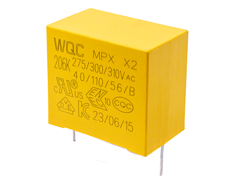
Capacity and voltage range from low to high, widely distributed. Can be applied to lighting and consumer electronics.
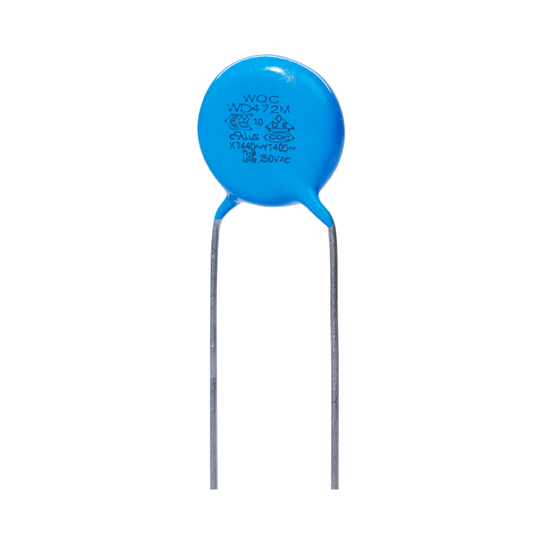
Capacity and voltage range from low to high, widely distributed. Can be applied to lighting and consumer electronics.
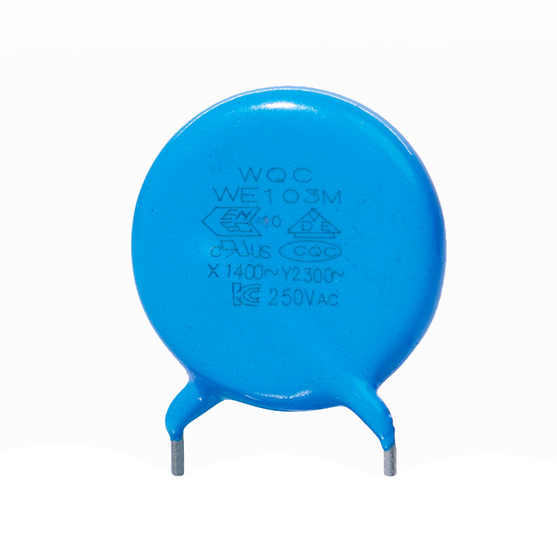
Capacity and voltage range from low to high, widely distributed. Can be applied to lighting and consumer electronics.
-
-
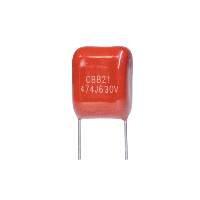
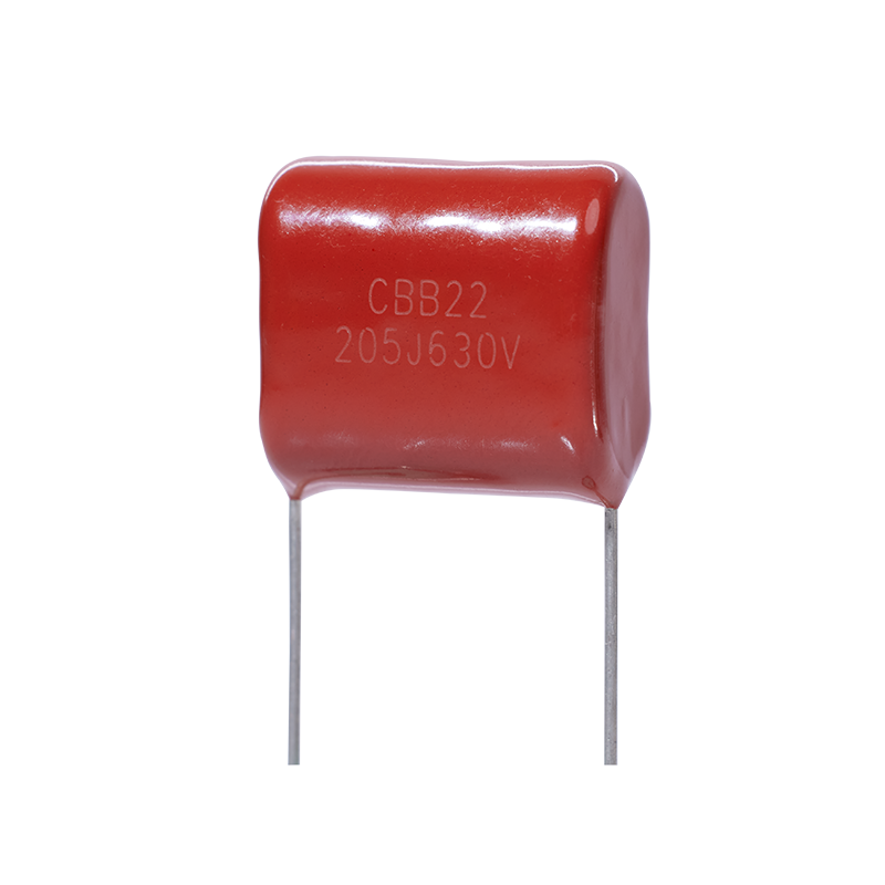
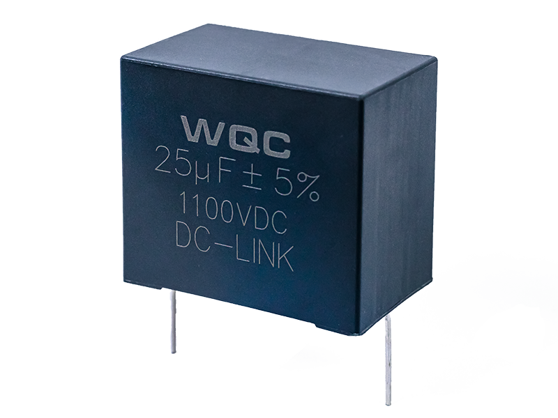
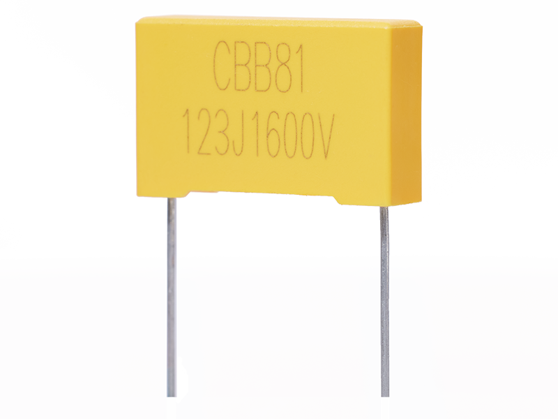
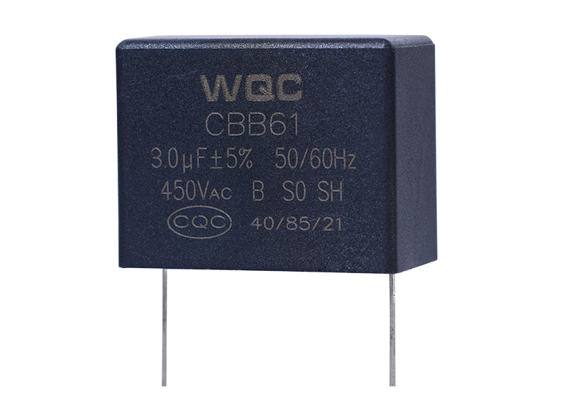
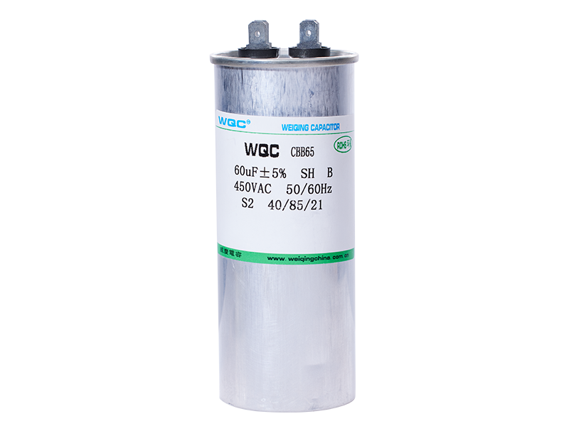
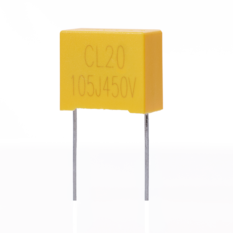
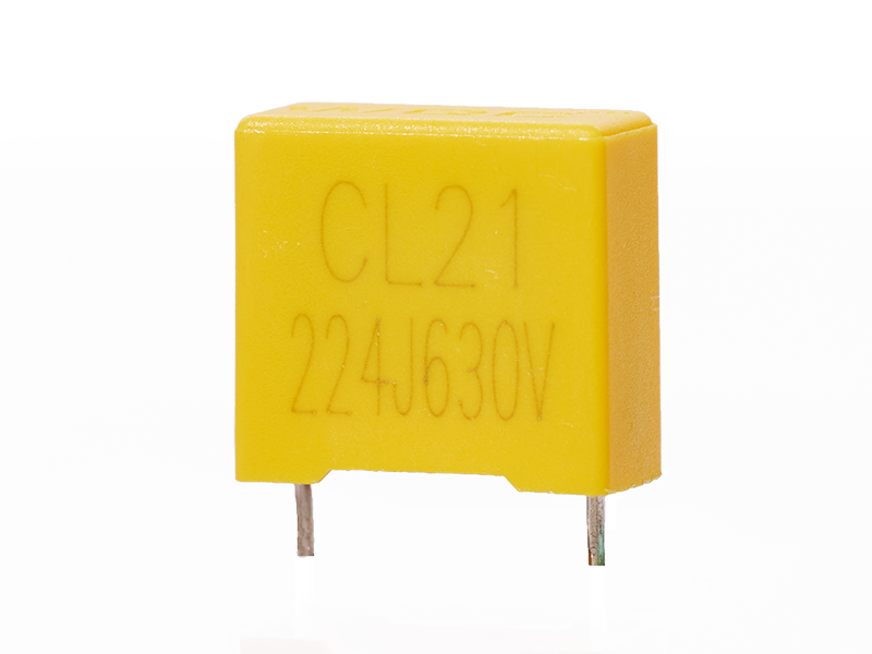
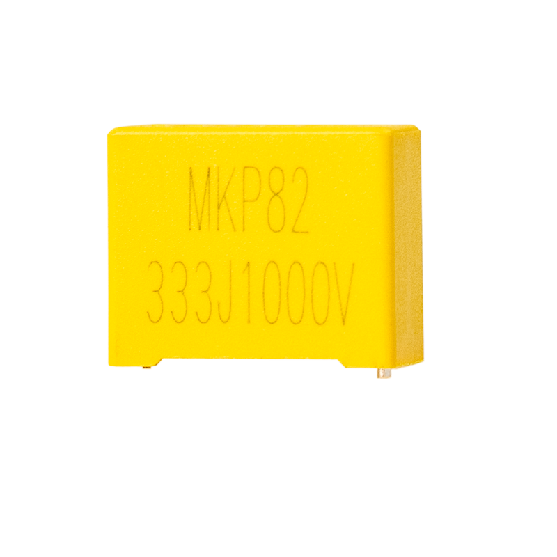
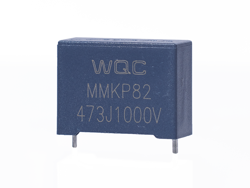
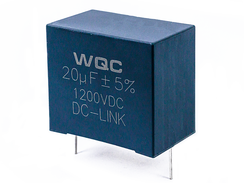
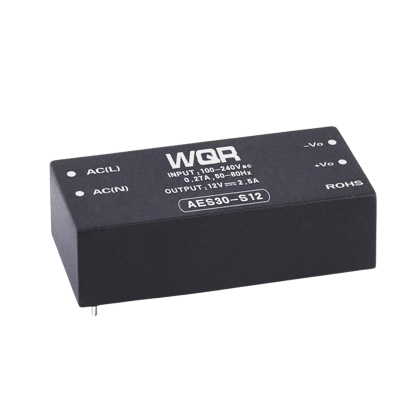
RC with resistor and capacitor
Classification:
- Voltage (AC): 275/300/310Vac
- Capacity (uF): 0.001μF~25μF
- Diameter (mm): 6mm~35mm
- Width (mm): 9mm~28mm
- Height (mm): 12mm~50mm
- Foot distance (mm): 10mm-15mm-22.5mm-27.5mm
- Maximum temperature (° C): 110℃
- Minimum temperature (° C): -40℃
Key words:
capacitor
Product Description
RC with resistor and capacitor
What is an RC capacitor? A capacitor that charges through a resistor R when the power supply Vu is applied is called an RC capacitor. It is also referred to as an RC filter, which consists of a resistor and a capacitor. RC filters come in low-pass and high-pass varieties, and their cutoff frequency is calculated using the formula: F(cutoff) = 1 / (2πRC). The cutoff frequency is the point at which the filter’s frequency response exhibits a turning point. This capacitor is manufactured by winding polypropylene film material and completing preliminary processing steps, followed by gold‑plating on both sides of the capacitor. It is then assembled with resistors and capacitors of various values, resulting in either series or parallel configurations.
Message
Professional service team answers
Service Hotline:
Contact
Phone: +86 13826981362
Tel:+86 076988956188
E-mail: wqc001@weiqingchina.com.cn
Address: Weiqing Electronics Co., Ltd., Floor 1, Building 12, No.7, Science and Technology 10th Road, Songshan Lake High-tech Development Zone, Songshan Lake Administrative Committee, Dongguan City, Guangdong Province
Mobile Website

Scan Consultation